- 您现在的位置:买卖IC网 > Sheet目录1228 > MAX5498EVKIT+ (Maxim Integrated Products)KIT EVAL FOR MAX5498
�� �
�
�MAX5498� Evaluation� Kit�
�Command� History�
�The� Command� History� group� box� displays� the�
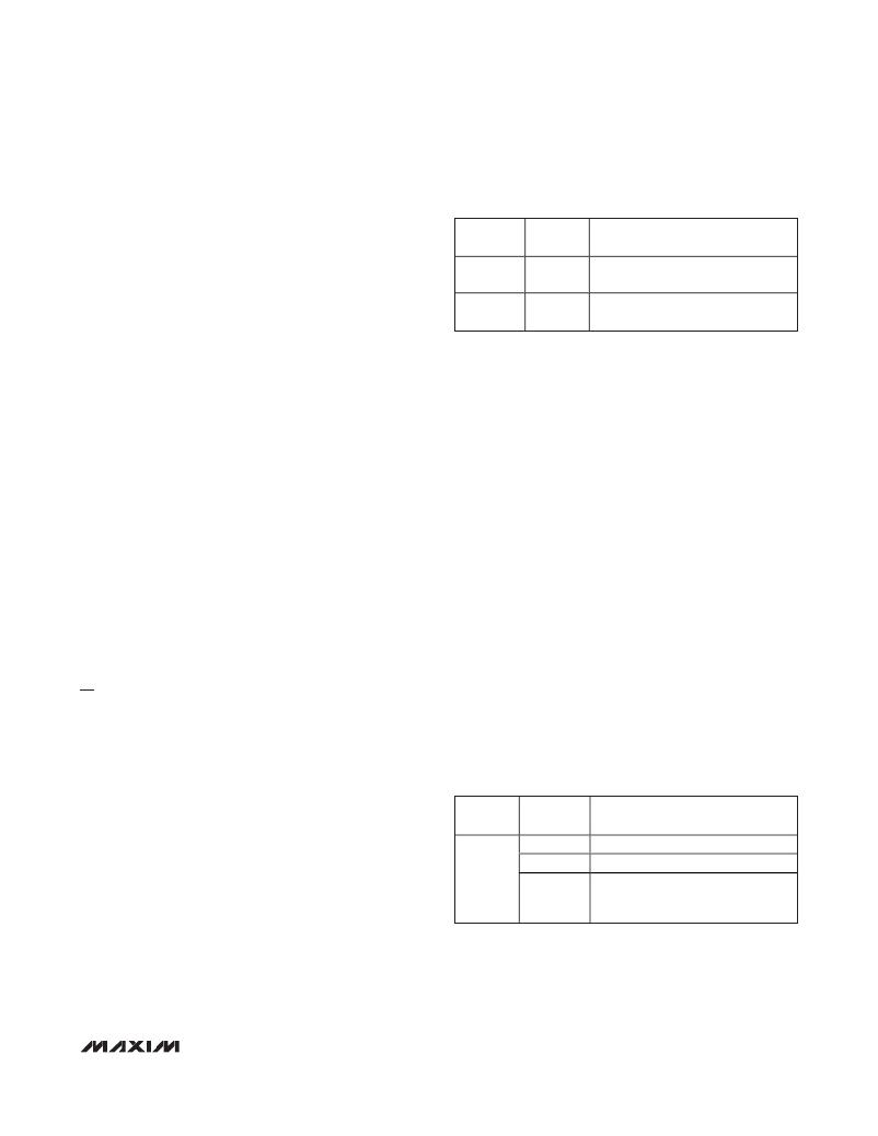
�Table� 2.� J1� and� J2� Shunt� Configuration�
�sequence� of� bytes� sent� to� the� device� for� each� of� the�
�GUI’s� button� controls.� For� the� write� controls� (� Write� and�
�Write� NV� ),� the� group� box� displays� the� command� byte� fol-�
�lowed� by� the� 2� data� bytes� (wiper� setting).� The� 2� data�
�bytes� correspond� to� the� W-L� tap� value.� For� the� save,�
�load,� and� copy� controls� the� group� box� displays� the� asso-�
�ciated� command� byte.� All� values� are� displayed� in� hex.�
�SHUNT�
�POSITION�
�3-4*�
�Not�
�installed�
�PIN�
�L1,� L2�
�L1,� L2�
�DESCRIPTION�
�L� terminals� connected� to� GND� (use�
�when measuring digital pot resistance)�
�L� terminals� unconnected�
�*Default� position.�
�Evaluating� Other� Devices�
�The� MAX5498� EV� kit� software� can� also� be� used� to�
�evaluate� any� of� the� other� devices� in� the� MAX5494� –�
�MAX5499� family.� The� software� is� reconfigured� for� each�
�device� by� choosing� the� device� number� from� the�
�Options� |� Device� menu� bar.� To� ensure� proper� opera-�
�tion,� install� the� alternate� device� on� the� EV� kit� before�
�reconfiguring� the� software.�
�Keyboard� Navigation�
�When� you� type� on� the� keyboard,� the� system� must� know�
�which� control� should� receive� the� keys.� Press� the� Tab�
�key� to� move� the� keyboard’s� focus� from� one� control� to�
�the� next.� The� focused� control� is� indicated� by� a� dotted�
�outline.� Shift� +� Tab� moves� the� focus� to� the� previously�
�focused� control.� Buttons� respond� to� the� keyboard’s�
�space� bar.� Some� controls� respond� to� the� keyboard’s� up�
�and� down� arrow� keys.� Activate� the� program’s� menu� bar�
�by� pressing� the� F10� key,� and� then� press� the� letter� of� the�
�menu� item� you� want.� Most� menu� items� have� one� letter�
�underlined,� indicating� their� shortcut� key.�
�Detailed� Description� of� Hardware�
�As� configured,� the� MAX5498� EV� kit� evaluates� the�
�MAX5498� dual,� linear-taper� potentiometer� with� one�
�programmable� voltage-divider� and� one� variable� resis-�
�tor.� The� potentiometer� terminals� are� accessible� from�
�headers� H1� and� H2.� The� MAX5498� EV� kit� hardware� and�
�software� can� also� be� used� to� evaluate� the� MAX5494–�
�MAX5497� or� MAX5499.� The� installed� device� is� con-�
�trolled� using� a� graphical� user� interface� (GUI)� that� can�
�be� downloaded� by� visiting� www.maxim-ic.com/evkitsoft-�
�Evaluating� the�
�MAX5494–MAX5497� or� MAX5499�
�To� evaluate� the� MAX5494–MAX5497� or� MAX5499,� con-�
�tact� the� factory� for� a� free� sample� of� the� MAX5494ETE+,�
�MAX5495ETE+,� MAX5496ETE+,� MAX5497ETE+,� or�
�MAX5499ETE+.� Refer� to� the� MAX5494–MAX5499� IC�
�data� sheet� for� additional� device� information.�
�External� User-Supplied� SPI� Interface�
�The� MAX5498� EV� kit� can� be� modified� for� use� with� an�
�external� user-supplied� SPI� interface.� First,� with� power�
�off� and� USB� disconnected,� turn� the� board� over� and� cut�
�the� four� traces� that� are� on� the� back� of� the� board,� under-�
�neath� location� J3.� Install� a� standard� dual-row� header�
�and� connect� an� external� SPI� interface.� See� Figure� 2a�
�for� the� J3� schematic� and� Figure� 4� for� J3� trace� locations�
�on� the� bottom� side� of� the� PCB.�
�Single-Supply� Operation� (VDD)�
�The� MAX5498� EV� kit’s� default� configuration� is� for� single-�
�supply� operation.� The� USB� interface� and� microcontroller�
�are� powered� from� the� USB� bus� voltage� (5V).� The� device�
�under� test� can� be� powered� from� an� external� power� sup-�
�ply� (2.7V� to� 5.25V)� connected� between� VDD� and� GND�
�(see� Table� 3).� When� operating� with� a� single� supply,� the�
�VSS� input� should� be� connected� to� GND� (Table� 4).�
�Table� 3.� JU1� Jumper� Functions�
�SHUNT�
�SIGNAL� EV� KIT� FUNCTION�
�POSITION�
�ware� and� clicking� on� the� MAX5498� EVKIT� software� link.�
�1-2*�
�Power� device� from� USB� 5V� supply.�
�Ground� Referencing� Test� Equipment�
�The� L� terminals� of� each� digital� pot� are� linked� to� ground�
�by� placing� a� shunt� on� pins� 3-4� of� headers� J1� and� J2�
�VDD�
�Open�
�2-3�
�Do not use—device will not be powered.�
�Power� device� from� external� power�
�supply� (2.7V� to� 5.25V)� connected�
�(see� Table� 2).� This� provides� a� ground� reference� when�
�using� nonground� referenced� test� equipment� (e.g.,�
�handheld� digital� multimeter).�
�*Default� position.�
�between� VDD� and� GND� pads.�
�_______________________________________________________________________________________�
�5�
�发布紧急采购,3分钟左右您将得到回复。
相关PDF资料
MAX5946LEVKIT
EVAL KIT FOR MAX5946
MAX5960LEVCMAXQU+
KIT EVAL FOR MAX5960
MAX5969AEVKIT#
EVAL KIT MAX5969A
MAX5970EVKIT+
EVAL KIT MAX5970
MAX5976BEVKIT+
EVAL KIT MAX5976B
MAX5977AEVKIT#
EVAL KIT MAX5977A
MAX5980EVKIT#
EVAL KIT MAX5980
MAX5982CEVKIT#
EVAL KIT MAX5982C
相关代理商/技术参数
MAX5499ETE
功能描述:数字电位计 IC RoHS:否 制造商:Maxim Integrated 电阻:200 Ohms 温度系数:35 PPM / C 容差:25 % POT 数量:Dual 每 POT 分接头:256 弧刷存储器:Volatile 缓冲刷: 数字接口:Serial (3-Wire, SPI) 描述/功能:Dual Volatile Low Voltage Linear Taper Digital Potentiometer 工作电源电压:1.7 V to 5.5 V 电源电流:27 uA 最大工作温度:+ 125 C 安装风格:SMD/SMT 封装 / 箱体:TQFN-16 封装:Reel
MAX5499ETE+
功能描述:数字电位计 IC 10-Bit Dual NV Linear-Taper RoHS:否 制造商:Maxim Integrated 电阻:200 Ohms 温度系数:35 PPM / C 容差:25 % POT 数量:Dual 每 POT 分接头:256 弧刷存储器:Volatile 缓冲刷: 数字接口:Serial (3-Wire, SPI) 描述/功能:Dual Volatile Low Voltage Linear Taper Digital Potentiometer 工作电源电压:1.7 V to 5.5 V 电源电流:27 uA 最大工作温度:+ 125 C 安装风格:SMD/SMT 封装 / 箱体:TQFN-16 封装:Reel
MAX5499ETE+T
功能描述:数字电位计 IC 10-Bit Dual NV Linear-Taper RoHS:否 制造商:Maxim Integrated 电阻:200 Ohms 温度系数:35 PPM / C 容差:25 % POT 数量:Dual 每 POT 分接头:256 弧刷存储器:Volatile 缓冲刷: 数字接口:Serial (3-Wire, SPI) 描述/功能:Dual Volatile Low Voltage Linear Taper Digital Potentiometer 工作电源电压:1.7 V to 5.5 V 电源电流:27 uA 最大工作温度:+ 125 C 安装风格:SMD/SMT 封装 / 箱体:TQFN-16 封装:Reel
MAX5499ETE-T
功能描述:数字电位计 IC RoHS:否 制造商:Maxim Integrated 电阻:200 Ohms 温度系数:35 PPM / C 容差:25 % POT 数量:Dual 每 POT 分接头:256 弧刷存储器:Volatile 缓冲刷: 数字接口:Serial (3-Wire, SPI) 描述/功能:Dual Volatile Low Voltage Linear Taper Digital Potentiometer 工作电源电压:1.7 V to 5.5 V 电源电流:27 uA 最大工作温度:+ 125 C 安装风格:SMD/SMT 封装 / 箱体:TQFN-16 封装:Reel
MAX549AC/D
功能描述:数模转换器- DAC RoHS:否 制造商:Texas Instruments 转换器数量:1 DAC 输出端数量:1 转换速率:2 MSPs 分辨率:16 bit 接口类型:QSPI, SPI, Serial (3-Wire, Microwire) 稳定时间:1 us 最大工作温度:+ 85 C 安装风格:SMD/SMT 封装 / 箱体:SOIC-14 封装:Tube
MAX549ACPA
功能描述:数模转换器- DAC Integrated Circuits (ICs) RoHS:否 制造商:Texas Instruments 转换器数量:1 DAC 输出端数量:1 转换速率:2 MSPs 分辨率:16 bit 接口类型:QSPI, SPI, Serial (3-Wire, Microwire) 稳定时间:1 us 最大工作温度:+ 85 C 安装风格:SMD/SMT 封装 / 箱体:SOIC-14 封装:Tube
MAX549ACPA+
功能描述:数模转换器- DAC 8-Bit 2Ch Precision DAC RoHS:否 制造商:Texas Instruments 转换器数量:1 DAC 输出端数量:1 转换速率:2 MSPs 分辨率:16 bit 接口类型:QSPI, SPI, Serial (3-Wire, Microwire) 稳定时间:1 us 最大工作温度:+ 85 C 安装风格:SMD/SMT 封装 / 箱体:SOIC-14 封装:Tube
MAX549ACUA
功能描述:数模转换器- DAC RoHS:否 制造商:Texas Instruments 转换器数量:1 DAC 输出端数量:1 转换速率:2 MSPs 分辨率:16 bit 接口类型:QSPI, SPI, Serial (3-Wire, Microwire) 稳定时间:1 us 最大工作温度:+ 85 C 安装风格:SMD/SMT 封装 / 箱体:SOIC-14 封装:Tube